Sunday, August 11, 2013

Extruded, beveled text in Houdini: au automated approach

Mattias Lindberg asked for a new solution to the problem of adding a bevel to extruded text, and I am happy to oblige. The problem with my old solution is that it was manual, requiring work for each letter. Remember this diagram?

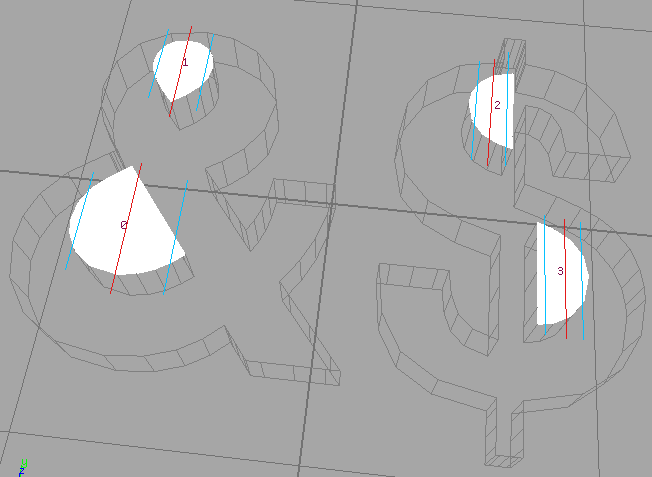
Slice, bevel each, trim each, join.
Simple enough, but where to cut?

The diagram displays three carefully-selected slice locations: far enough from each other to avoid artifacts, but sufficiently close to overlap with both holes. Can we get away with simpler, automated cuts?

Of course we can. This is Houdini, we can automate anything!

Strategy

I would like to slice one hole at a time, from left to right. Enumerating the holes is surprisingly easy: once you turn off the Extrude SOP's "Hole Polygons" option, columns representing the holes appear!

Those "hole columns" sure are convenient now,
but I wonder what is their true purpose?

The next step is to compute knife positions for each hole. We need three slices per hole: one in the middle, and two on the sides.

Each slice crosses its hole, in order to break the
surrounding holed polygon into two regular polygons.

Some of the slices from one hole will cut through other holes, but that's okay. The three manually-placed slices in the ampersand example demonstrates that cutting many holes with one slice is perfectly fine, and having more than three slices per hole will simply divide the same work into a larger number of smaller pieces.

Once we have picked our slice locations, we need to bevel each segment individually, chop off the sides, then merge the results.

Slice everywhere, bevel everywhere, trim everywhere, join.
A flawless dollar-making plan!

Where to draw the lines

Given the location of all the holes, how do we tell Houdini where to perform the slices? Our goal is to generate one point at each of the locations at which we want to slice, like this:

Approaching, but not touching, the boundaries of each hole.

A number of SOP nodes can be used to obtain this arrangement of points, but the simplest is to use Add.

Protip: don't forget to set your expression language to HScript
(the black H icon in the upper right)

The above expressions place the three points at the left, middle, and right ends of the current geometry's bounding box. Of course, if we want those three points to surround a hole, the geometry must be changed to contain nothing but the hole, so the Add SOP needs to be placed inside a ForEach. Also, Add will add the points to a geometry which already contains the hole, so in order to isolate the three new points, the points which define the geometry of the hole must be removed.

Since we are inside a ForEach SOP, the offending points are all vertices of the only polygon in the mesh. It sounds like Delete primitive 0 should do the job, but in Primitive mode, the Delete SOP deletes any point which doesn't belong to any primitive, regardless of the any other options you set. Blast does the same. We must instead work in Point mode, deleting the range 0 to $N-3, in order to keep only our three new points.

Finally, we must scale down each triplet by a small amount, so that the points don't touch the sides of the holes. You might be tempted to use a Transform SOP, but I suggest the Primitive SOP instead: it supports all the typical Transform options, but it also pre-fills the pivot to the centroid of each primitive. This way, scaling down the points will bring them closer to the center of the hole, instead of closer to the origin of the scene. Since we have just used Delete to get rid of our only primitive, we need to place the Primitive SOP before the ForEach node.

A sliding window of slices

Now that we have our slice positions, we can start slicing! The purpose of those slices is to separate the polygons into simple shapes, for which no spurious hole-supporting segments are necessary.

Holes are implemented by adding those spurious segments.
If you imagine those segments to be tiny gaps, with one small
segment on each side, then you can follow along the perimeter
of each symbol and visit every single point, including the holes. 

By slicing each letter into sufficiently-small pieces (smaller than the holes), we can guarantee that each segment is a regular polygon, that is, a polygon with no holes nor spurious segments. We obtain the pieces using another ForEach, in Number mode this time. Extract each piece by slicing the geometry on the left and right, computing the position of each slice using the positions of the ith and (i+1)st points. The python expression for this is surprisingly long:

i = int(node("..").stampValue("FORVALUE", 0))
p = node("../null1").geometry().points()[i+1]
return p.position()[0]

Each colored polygon is regular.
The spurious segments are gone! Hurray!

In the above image, there was only one slice per hole. This is sufficient to obtain regular polygons, but applying the Extrude and PolyBevel SOPs to each of those polygons is not going to produce an appropriate bevel for the combined shape.

Each piece is perfectly beveled,
but the slices are way too visible.

Instead, a workaround is to cut larger, overlapping pieces, before trimming the needlessly-bevelled sides. To do this, simply create your pieces using the ith and (i+3)rd points, bevel, then trim along the (i+1)st and (i+2)nd points. Effectively, this is a sliding window of size 4, iterating over all slice positions from left to right:

Each piece is now as wide as three of our previous pieces,
but we will trim the sides so only the middle section remains.

However, as the above animation clearly demonstrates, the pieces produced by this strategy are way too large! They are large enough to span multiple holes, causing them to contain those nasty spurious segments which ruin our bevels. To produce narrower pieces, we need to slice more often; this is why, in the previous section, we produced three slice locations per hole instead of one.

Three slices per hole is the ideal number: any fewer, and we risk to contain a hole. With only two slices, for example, the piece which is centered around those two slices ranges from one slice to the left of those, most likely beyond the left edge of the hole, all the way through once slice to the right of the central slices, most likely beyond the right edge of the hole. With three slices, we don't have this problem. Whether the central slices are the first or the last two, one of the two sides of the piece will lie along the third slice, thereby guaranteeing that the hole is cut open.

Left: The regular PolyBevel SOP has issues with holes.
Right: Our sliding window approach handles holes gracefully.

Mysterious vertical lines

Let's try to apply our automated bevelling algorithm to a larger chunk of text.

Top: The regular PolyBevel SOP has issues with holes.
Right: Our sliding window approach handles holes gra...
wait, what are those vertical lines?

Strangely enough, the algorithm described so far only exhibits its imperfections when applied to text which span more than one line. How is this possible? Let's zoom in.

The line cuts through all the letters at the exact same position.
Could it be one of our slices? Or should I say... two of our slices?

Have you guessed yet? The problem occurs when two holes accidentally align. Then, the slice positions we compute for the two holes also coincide. But then, when the sliding window's third and fourth points coincide, trimming the geometry between those two points has no effect! The needlessly-bevelled side fails to be trimmed, and remains instead embedded inside the result geometry.

From left to right (cross-section): slice at points 1 and 4, bevel, slice at points 2 and 3.
Second row: same thing, but points 3 and 4 are close, so the bevel remains visible after the trim.

Consolidating points

To avoid the problem highlighted in the previous section, we need to prevent consecutive slices from being to too close to each other. Quick: which Houdini SOP removes points which are too close from each other?

The Facet SOP can also make primitives look more
flat, remove superfluous points along a curve, correct
polygons, compute and/or correct normals, ...

One slight obstacle is that while our slices are too close along the X axis, the points which represent those slices might be far away along Y or Z.

The slices (in black) are way too close, but
the distance between the points (in green)
is actually quite large.

One easy fix is to squash the Y and Z coordinates down to zero, using XForm or Point. The disadvantage of this method is that it's hard to visualize the results, as the points end up far from their corresponding holes.

Can you guess which point corresponds to which hole?
Hint: see the previous image.

Recovering the original position of the points after some of them were removed by Facet is surprisingly easy. Just store the position in a custom attribute!

Another subtlety is that Facet deletes points which are not
part of any primitive, so we need to Add then Delete a primitive
which goes through all points, i.e. "polygon 0 = *".

The distance given to the Facet SOP is very important: if the distance is too small, some vertical lines will slip through, while if it is too large, we might miss some of the holes. I used twice the bevel amount, with excellent results:

No imperfections anywhere!
Don't believe me? Click to inspect the high-res version.

Conclusion

Trying to solve a concrete issue encountered by a reader was quite entertaining. Do you have an issue to be solved? Tell me in the comments!

Sunday, October 7, 2012

Particles aren't Particularly Pretty

This week, I explored the Particles tab of the Geometry context. I had very high expectations about particles; I know that particle effects can be very impressive, and I know that Houdini animators are in high demand precisely because of the software's great support for particles.

This short list of nodes has a great potential.
Or does it?

Well, I was quite disappointed.


The main problem with particles, in my opinion, is the tradeoff between control and randomness. When creating particles, the default is to create particles at each point in the geometry, in the order of the point numbers. This causes the particles to appear in rank and file, which doesn't look right. By randomizing the point numbers (using the Sort node), the particles look much better, but we lose a lot of control. The particles appear at different positions and move in different directions, which leads to some regions ending up cluttered, and others ending up empty. Not having any control over which regions is really annoying, because that has a big effect on the visual organization of the scene.

Left: Particles created in an orderly fashion are predictable, but look boring.
Right: Particles created randomly look much better, but are less predictable.


I hope that those problems are partly due to the fact that I am using particle operators in a Geometry context instead of a Particle context. The 6 geometry nodes I have explored today are a bit limited, but there are still 67 more particle-related nodes to explore in the Particle context! Allow me to explain.

Houdini has a few different kinds of networks, which are used for different purposes. The one I most want to learn is the Geometry context, which is used to manipulate the shape of the objects in the scene. I still have 189 nodes to explore there. Other contexts are used to define which materials they are painted with, how they move, and how they interact with each other. One of those, the Particle context, is entirely dedicated to particles. I expect that learning the 67 nodes from that context would allow me to create better-looking results than the mediocre trinkets I managed to create this week.

6 down, 189 to go!
I'll do better next time.

67 nodes doesn't look so big compared with the number of Geometry nodes I still have to learn, but for once, I'll try to finish what I have started!

Sunday, September 30, 2012

Tools for curved surfaces

I have a love-hate relationship with NURBS. I love them for the same reason I like vector art: they scale to arbitrarily-high resolutions. I hate them because the NURBS tools often produce ugly artifacts, and it's not obvious how to fix them.


In two dimensions, curves are approximated using a large number of square pixels: zoom in too much, and you'll see the pixels. Vector-based images don't have this problem because they store the curves themselves, not the pixels.

Above: pixels.


In three dimensions, curved surfaces are approximated using a large number of flat faces: zoom in too much, and you'll see the triangles. NURBS-based geometry doesn't suffer from this problem because it stores the curves themselves, not the triangles.

Above: polygon edges.


This all sounds great in theory, but when I experimented with the Houdini tools in the NURBS category, I was repeatedly disappointed by unexpected artifacts in the generated curves. Sometimes the artifacts were tiny, but visible — and sometimes the generated curves were completely wrong. In both cases, there was no obvious way to fix the problem.

Left: subtle artifact.
Right: not so subtle.


As you can see below, eventually I did manage to produce some good-looking shapes. There was no magic artifact-fixing step; I sat down and learned how each tool worked, how they were calculating their results. This allowed my to understand why I saw the artifacts I saw, and guided me towards ways of using the tools which were less likely to generate artifacts. It's better to stick to profile-curves generated through the Carve tool, for instance.

17 down, 195 to go!
Yes, I know there are 20 icons,
but some of those have appeared before.

Oh, and one of those tools doesn't exist,
it's a digital asset I created myself.
Can you spot which one? 

I learned a lot during this series, but I still have many more tools to go through. Houdini has a lot of stuff!

Saturday, September 8, 2012

The tools from which everything else is built

In my quest to learn all of Houdini's 252 Geometry tools, I have explored the 32 node types listed in the Manipulate submenu.

Above: the Manipulate submenu.

I thought these would just be steps 9 through 40 of a long and boring quest of knowledge, but no! I discovered some very important tools in there, and I might never have discovered them if I had not tried to learn every single one of them.

The best example of a well hidden gem is the SSS Scatter node. Neither its icon, its name, or even its documentation gives any indication of what it does.

Poor SSS Scatter probably doesn't get much use.
Its icon hasn't been updated to the new style...
and its documentation is pink, for some reason.

If I wasn't trying to go through the entire list of tools, I would never have tried the SSS Scatter node. When I want to implement a particular effect, I look through the list of names, trying to guess which one could help me; but "SSS Scatter" never sounds like what I am looking for, regardless of what I am looking for. So, what does the darn node do, anyway?

It gives chickenpox.

It creates points all over the object's surface! Very useful-looking. I hope that, among the remaining 212 nodes, there is a version which creates points all over an object's volume, too.


The other reason why there are some useful nodes which I wouldn't have discovered otherwise is that so many of those nodes are redundant. There is a Twist node, for example, which does exactly what it says on the tin. Many 3D packages have a Twist modifier, because in those packages, that's the only way to twist objects; in Houdini, however, twisting an object doesn't need to be a primitive operation.

Twisting is a simple mathematical transformation, whereby points are rotated around an axis by an angle which varies along the length of the axis. I could implement that using the Point node, which applies a mathematical formula to each point of an object. Of course, writing a mathematical formula is much harder than using a pre-existing Twist node; the point is that being able to write any mathematical formula is much more powerful than having to pick among a list of pre-existing nodes. It's the powerful nodes in which I am interested, but they are buried under so many redundant nodes like Twist.


In the Manipulate category, I found three powerful nodes of that kind: Point, Primitive, and VOP SOP. The Point node, as I have already described, allows mathematical transformations to be evaluated on all points. The Primitive node is similar, except it works on faces instead of points. And, last but not least, the VOP SOP. Again, not a very descriptive name nor icon, but how much raw power!

Like the Point node, the VOP SOP also applies a transformation to all points. But instead of using a hard-to-read and hard-to-write mathematical formula, you can double-click on the VOP SOP node to dive inside and manipulate a sub-network. There is a whole new world with 229 extra node types in there!

32 down, 212 to go.
Plus 229 inside the VOP SOP sub-network.
Plus 74 at the scene level, 98 at the channel level,
138 at the compositing level, 41 at the render level,
67 at the particle level, 56 at the texture level,
264 at the dynamic level...


At this rate, I don't think I will ever master all of Houdini's nodes.

Monday, September 3, 2012

The first eight tools

One trinket for each tool in the Edge category.

After I discovered that development time is linked to familiarity, not complexity, I began a quest: I want to become familiar with all of Houdini's 252 geometry nodes, one at a time. Here are the first eight.

The goal is not to visually represent the effect of each node; Houdini already has node icons for that purpose. Instead, the goal is to for me to play with each tool, getting a feeling for what it does, and combining it with other nodes in order to get a simple, but nice-looking result. If you want to follow along, I recommend that you try to reproduce my trinkets, with no other indication than the picture of the final result and the name of the main tool I wanted to illustrate. Trying to get to a specific result will be harder than just trying to get something nice, but the extra challenge will be worth it: learning how to use a piece of software as a game, through a series of challenges is much more stimulating and rewarding than aimless experimentations. It's true! I'd go back in time and challenge my two-hours-younger self with the above image, if I could.

For the rest of this post, I would like to reveal the steps necessary to create the parts of this image which are not part of the game. This part, I am sending to my future self, in case I forget the intricacies.


First, the lighting. There is no light. When there is no light, Houdini adds a default light behind the camera, and that's what you see here. Except for this:

Artificial shadows.

By default, Houdini doesn't render any shadow. This causes the inside of the sphere to have the same color as its outside, which in turn makes the 3D shape hard to see. I'm sure there must be a way to somehow turn on shadows, but for now, I used a trick: I painted the inside of the sphere in a darker shade than the outside of the sphere.

If this was a real physical object, that would be it: the two sides of the sphere would be distinct, and I could paint each side a different color. Virtual spheres, however, store their color in their vertices, and that color is used by both sides.


Implementing a two-sided material was harder than I thought, but in the end it thought me a lot, and I am glad that Houdini does things this way. In any other 3D application, I would be looking through the material options, looking for a "backface color" field or something like that. If I succeed at finding the button, then the problem would be solved, and I would then know how to make two-sided surfaces. If an extensive search revealed that there was no such button, then it would mean that two-sided surfaces are not supported by the application, and I'll have to live without them, end of story.

In Houdini, however, giving up is never the solution. I wish more applications were like that.

After I failed to find the button, I double-clicked the default Clay material to see how it was implemented. I played with the wires, unplugging and re-plugging them to see what they were doing, and that allowed me to figure out which one was responsible for the color. I tried to force a green color, to see if I knew what I was doing, but the entire surface became flat — clearly, that was the wrong place to interfere. I continued to investigate, and found another plug which yielded a better result. Aha! That's where I should plug my two-sided apparatus.

Playing with wires.

I then added a few nodes to check whether the surface normal is pointing towards the camera, and if not, to darken the color by an adjustable amount. At each step of the way, I could debug my network by plugging an intermediate result into the color output and observing the rendered result. On that subject, an important remark: fancy materials like this one are only visible in the Render view, and not in the Scene view.


After the shader, I moved to the Compositing network in order to join all the inputs into a 2D table. In the past, I had exported all the individual images and layed them out in Gimp, adding some text as needed. This strategy has the disadvantage of leaving the procedural realm. Once I render a 3D model and process the resulting image inside Gimp, it is too late to go back to the 3D model and make adjustments. Very often, I only notice erroneous details once the image has been posted on this blog; at that point, I either adjust the model, re-render, and re-process it inside Gimp, or, more often, I give up and hope nobody notices.

But why use Gimp? Houdini has procedural 2D tools, and the only reason I wasn't using them was because I wasn't familiar with them. I decided to fix that! It was again harder than I thought, but it was worth it, because I did change my models often afterwards.

The first step was to render the different models to different files. The easiest way to do that is to render a different model at every frame, and to render the animation to a sequence of files. I did this using a Switch node, switching to a different input at every frame.

Yup, that's a lot of inputs.

Then, we need to get this sequence into the Compositing network. I first tried a Render node, but it was always complaining about a failed render for some reason. I had to render to a sequence of files, then load them into my Compositing network using a File node. Even that was hard, because the renderer was quitting early, without writing the files. When that happens, the easy solution is to save and reopen the project (no need to quit Houdini).

Once I got the sequence of images inside the Compositing network, it was easy to arrange them into a table using the Mosaic node, and it was moderately easy to reorganize the images by reordering the inputs of the Switch node. The hard part was to add the text: there is a Font node, but it took me a long while to figure out that the reason I couldn't see the text was that it was rendering the font to a separate image plane! I can see how that could be useful, but I don't think it's a sane default.

Above: the reason why you can't see the output of your Font COP.


Finally, I added a few Subdivision and Facet nodes here and there to make the models look nicer, but alas! Once I turned off the Preview setting in the render pane to admire my high-quality renders, I saw a few inexplicable lines between faces which were supposed to be sharp.

Subtle, but annoying.

I still don't understand what is causing this, but the solution was to turn off Ray Variance Antialiasing, from the Mantra node's Sampling properties.


Hope this helps, future self!

Sunday, May 13, 2012

Why coding things takes so long

Work distribution has been... peculiar, this iteration. Observe.

  • Day 1: Completed all the two-box models I had scheduled for the iteration. Yay!
  • Nothing happens for a while.
  • Day 10: I've got so much time on my hands. Maybe I should do more work?
    Yes! I shall complete all the two-box models for the entire condo! Piece of cake!
    (writes down the task in the TODO list, then goes to sleep)
  • Nothing happens for a while.
  • Last day: Frantically creates two-box models for one extra room.
    Two more rooms left. Time's up; game over!

Well, now we know where most of the time went during this project.


For the next iteration, we intend to waste time in a totally different way. Because this time, it's a programming project! When programming, I think we tend to spend a disproportionate amount of time learning new libraries. Case in point: we want to parse OBJ files.

OBJ is a very simple file format for 3D meshes. Nadya asked me to look up how the OBJ format represents points on disk, and to write some pseudo-code for her. Well, I'm afraid I will again be done with my part of the work on the first day, because the format is very, very simple:

# this is a comment

# List of Vertices, with (x,y,z[,w]) coordinates, w is optional and defaults to 1.0.
v 0.123 0.234 0.345 1.0
v ...

The format is so simple that I don't really need to write down pseudo-code, but I will do so anyway, because I have a point to make.

m := create 3DS Max mesh object
for each line is the OBJ file:
  if the first character is 'v':
    split the line into words.
    x := second word
    y := third word
    z := fourth word
    add the point (x, y, z) to m's point list.

And that's it! That's the entire pseudo-code, because for this iteration, we're only interested in importing the points, not the faces.


Now, the algorithm is trivial, but we are still scheduling an entire 3 weeks to actually implement it. Why? Because we are not familiar with 3DS Max's API. We already know that the documentation contains errors. There might be all kinds of catches we haven't thought of and which we'll need to debug through. Really, the algorithm is trivial, but this has no incidence on the amount of time it will take to implement it! Familiarity with the necessary API is the dominant factor.

I feel like this is very representative of the work I do every day as a programmer. The reason coding things takes so long is not the complexity of the algorithms (they are often trivial), it's not that we work with low-level languages which force us to deal with unnecessary details (although we often do), it's mainly that we need to learn how to use new libraries all the time.

Well! I'll have a lot of time to ponder about that problem during the next three weeks. Because I'm responsible for the pseudo-code, and that part is done!


Oh, and I should also finish those two-box models. There are what, two rooms left? I think I'll wait until two days before the deadline...

Sunday, April 29, 2012

C# action item plugin for 3ds Max


It has been a while since the last time when I made some good progress on my 3D project. My guess is that I have had a lack of motivation and clear planning. And recently Sam has got a brilliant idea which should resolve most of my issues! We are doing Agile now!

Having a list of goals for a relatively short period is a good motivation for me: I work very well having visible and reasonable deadlines. And dealing with clear and shorter tasks helps to go forward with "baby steps". This is important given that I work on this project in my spare time.

So, here is my plan for this 3 week iteration! It has only one story: Creating a plugin that imports OBJ files into my scene.

You may want to ask - why do I need to create a whole plugin for a task that can be performed by simply clicking the Import menu? Well, due to our work process, I need a more sophisticated import procedure. I want to update the existing objects rather than delete and re-create them. Sam does modeling and I do texturing, and it is important to bring in his changes without deleting any material that are already in the scene.

So, my plugin will work in the following way. It will look up for the existing objects that are about to be updated and will rename them if necessary. Then it will proceed with the import. After the import is done, it will grab all the materials of the old objects and apply them to the new ones. After that, the old objects can be deleted.

This is the long term task. In this iteration I aim for a simpler goal: a simple, straightforward import of OBJ files. OBJ is a standard 3D object file format which we use to exchange files between our applications. I just want to familiarize myself with writing action item plugins and with the file import SDK.
And it is so super-easy to write these plugins with the new .NET SDK! I will show you how :)

First of all, I downloaded the Microsoft Visual C# 2010 Express from here. It is a free tool from Microsoft to create C# applications.

Then I went to the online SDK help to read how to create .NET plugins.

According to the help, I only needed to create an assembly project with a class that would implement the ICuiActionCommand interface. Once the dll is compiled, it should be placed to the bin\assemblies folder. The next time Max is launched, it will dynamically load it and register an instance of the class as an action in its CUI interface. Very simple!

In reality it was too, except that back then, when I started working on this, the online help had a bug. It said: "This is done by creating a public class that implements the interface ICuiActionCommand (found in MaxCustomControls.dll)". But it was not true! MaxCustomControls.dll did not have it! I searched all the help from the beginning to the end, and everywhere it was said the same thing. It was  pretty frustrating! Then I decided to text search my class name in the Max .NET assemblies, since they all have a textual description of the interface. And I found my class! It was hiding in the UiViewModels.dll, the namespace UiViewModels::Actions. UiViewModels was not documented at all; fortunately, this bug is fixed now.

I quickly implemented the action item interface, created a simple "Hello, World!" WPF form... And here is my action in 3dsMax!


I put a button with my action on the toolbar and launched the plugin:


Here is the code behind it (I omitted the window code, since it is trivial):


As you see, the code that launches the window is located in the Execute() function.
That's it! I am done with the action item plugin!

Now I need to write a simple import procedure, and this will be the subject of my next post.
Stay tuned!